PilotFish’s Automated Interface Assembly Line
The Key to Rapid Interface Configuration and Leveraging Reuse
The eiConsole for Healthcare features a 7-stage Graphical Assembly Line where you can build any interface, no matter how complex your integration requirements. It is natively self-documenting, so you’ll never have to worry again about who built an interface or who can maintain it.
In the eiConsole, each interface is constructed from a sequence of stages that are all graphically configurable without requiring any coding or scripting. Data Mapping is accomplished in a graphical 3-pane mapper using drag & drop, where even the most complicated mappings can be created (gone are the hairballs that line drawing mapping tools create). The eiConsole includes components that allow you to handle virtually every communication protocol, parsing, transformation or manipulation task you’ll ever need. Open source components may be leveraged, too, via our Open API – PilotFish offers the only commercially supported product that offers this tremendous advantage to easily and inexpensively extend functionality.
The eiConsole’s Graphical Automated Interface Assembly Line also makes it easy to leverage business analysts and non-developers who can do 80-90% of your interface work.
Stepping Through Building an Interface in the eiConsole
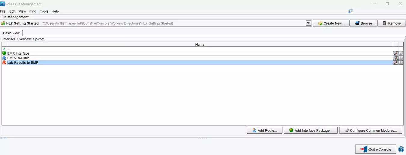
Step 1 – Create a New Interface or Route
When you open the eiConsole, the first screen is the File Management screen. This is where the interface route configuration files can be managed. PilotFish configurations are divided into two levels. A single connection between a Source and Target system is a route, and a collection of routes working together is an interface. In the File Management screen, existing interfaces are denoted by a green box icon and routes by a puzzle piece icon. Red indicates a configured interface and blue is an unconfigured interface.
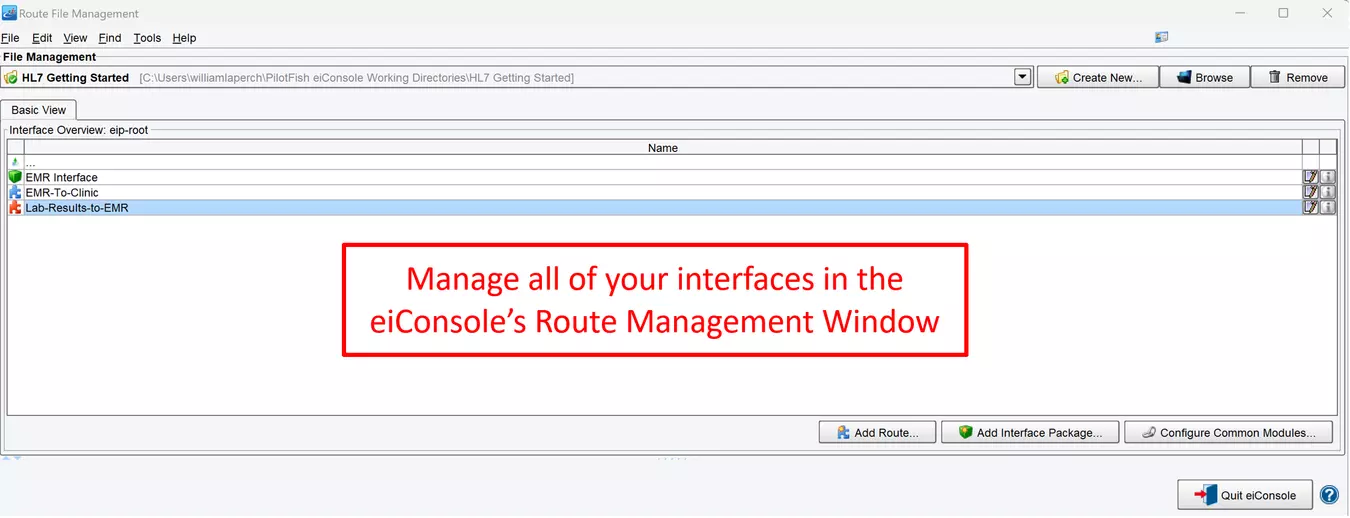
Click the Add Route button to create a new Route. Name it and click OK. Double-click your new Route to open the interface.
Step 2 – Review Route Building Grid
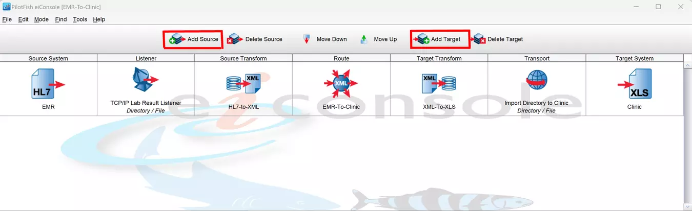
The eiConsole opens to the main Route or Interface Grid. (Note: The grid will be empty except for the Route stage when creating a new interface or route.) When developing integrations with the eiConsole, most of the work is done by building individual routes. In the eiConsole, a route connects a Source and Target system. There is no limit to the number of Source and Target Systems that can be linked this way.
In the eiConsole, routes are built configuring the stages of the Automated Interface Assembly Line. These 7 stages are laid out in a table at the top of the screen. These stages process the data flow from the Source System(s) to the Target System(s). Regardless of the type of integration or its complexity, each interface or route is created by stepping through and configuring each stage in the Assembly Line.
Step 3 – Define the Source and Target Systems
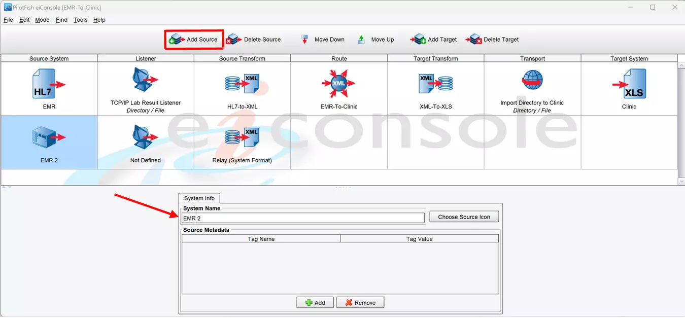
When building a PilotFish route, the first step is to add however many Source and Target Systems are required. Click the Add Source icon and fill in the bottom panel with your Source System (s) name. For easy reference, you should name your systems for what they are supposed to represent. Then click Add Target and name your Target System(s) following the same process.
Step 4 – Configure the Listeners and Processors
Click the Listener icon and select the Listener Tab. PilotFish retrieves data from the Source system using a component called a Listener. This component communicates with the Source system at highly configurable intervals, retrieves the data, and starts a PilotFish transaction. PilotFish comes pre-bundled with 40+ Listeners, capable of handling an extensive range of system types. Included are TCP/IP, Directory, HTTP Post, SOAP Web Services, etc.
Select a Listener from the drop-down list and fill in the configuration information for the type selected. In the example below, HL7 LLP is selected.
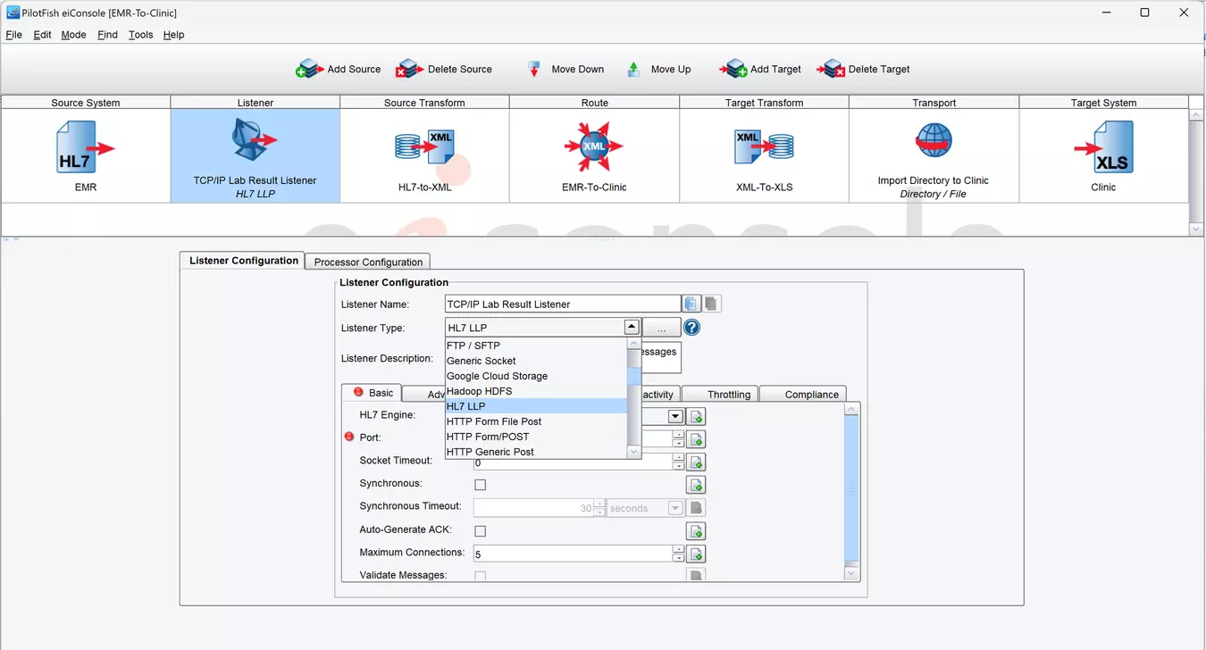
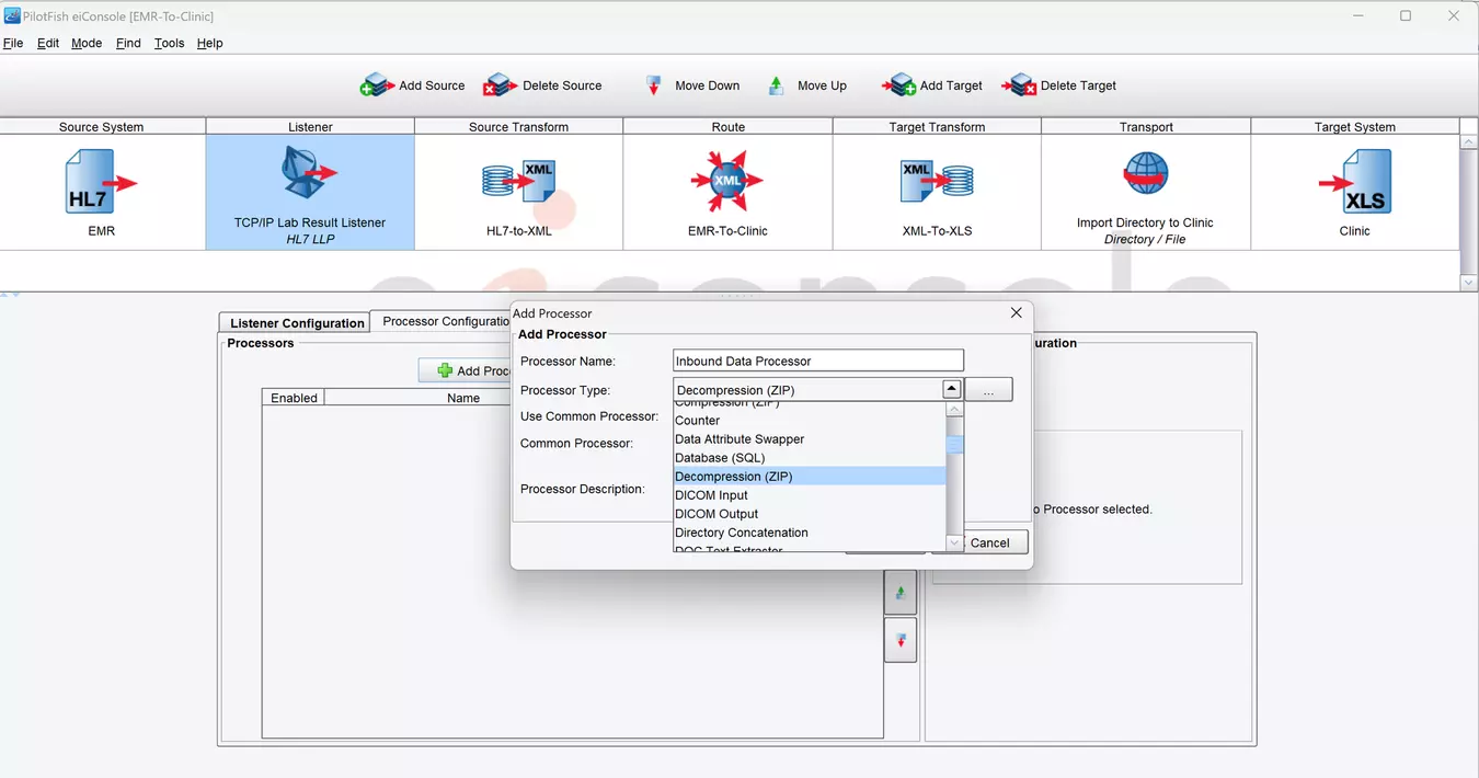
After adding a Listener, Processors can then be queued up to handle some initial data if required. PilotFish Processors run between several more significant stages to perform in-between operations. These can range from changing the encoding, handling encryption, compression/decompression, preserving metadata and so much more. View the extensive list of 140+ Processors available out-of-the-box or add your own using our Open API.
Step 5 – Transform Source Data to Common Standard
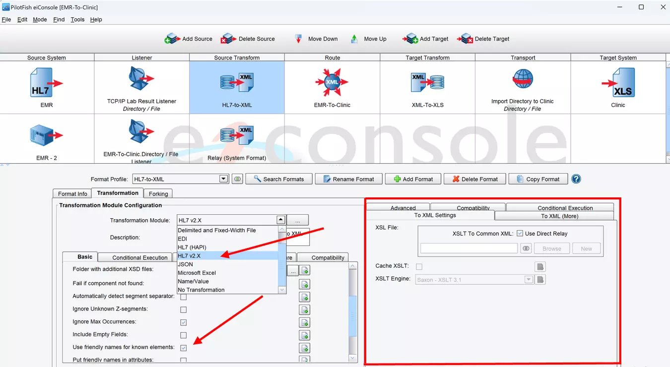
PilotFish works primarily with XML as it represents an easy-to-transform, common standard for working with data. Once the application receives data, it goes through this conversion process in two steps. First, if necessary, it goes through an automated Transformer to convert the raw content to XML. These Transformers are pre-built modules that can be set up through a simple graphical configuration. They take a wide range of standard data types and generate an XML representation of them. Among the included 30+ Transformers are:
- HL7 v2
- Fixed Width / Delimited Files (including X12 EDI)
- CSV
- XLS/XLSX
- Database Result Sets
In Healthcare, one of our most popular Transformers is our HL7 Transform. This is a lenient HL7 Parser capable of working with imperfect, extended, or non-standard message flavors of HL7. Configuration requires only changing a handful of options in the application.
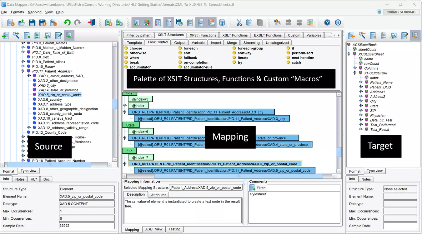
After the Transformer is configured, the data is mapped using XSLT. This logical mapping from one data structure to another is easily accomplished using the eiConsole’s Data Mapper. The eiConsole’s Data Mapper is a tool that generates W3C compliant XSLT using a simple, 3-pane, graphical, drag & drop interface.
Using the Data Mapper is simple. It involves loading sample files of the Source and Target formats and then dragging and dropping the content into the center panel to map them together. The pane on the left represents the Source format, the pane on the right represents the Target format, and the pane in the middle represents the relationship between the Source and the Target.
Above the main mapping panel, a panel of powerful XSLT functions and custom PilotFish add-ons provides more advanced functionality. If a developer wants to dive deep into the mapping process, an XSLT IDE tab is also provided for viewing and editing the code generated by the graphical mapping.
Step 6 – Configure the Routing Module
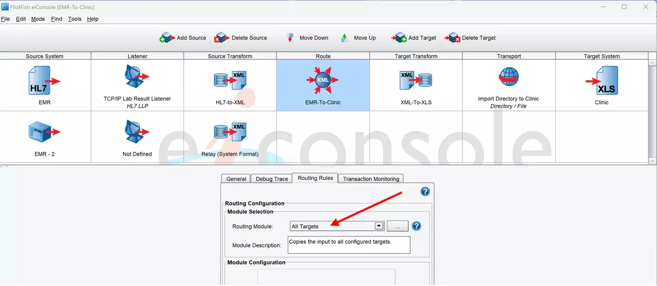
The Routing Module is the control point for the entire route. It is a gateway that determines which of the Target systems the data is sent to. The data can be sent to all Targets, or it can be restricted to one or several Targets using a series of Routing Rules that can be defined.
Also, the Routing Module controls the error handling for PilotFish. Should any errors occur while the route is processing, those errors are sent to a PilotFish Transaction Monitor. These components take the error and provide an alert that something has happened in a variety of different ways. As in all areas of the application, several pre-built Transaction Monitors have been provided.
A few examples of the transaction monitors included are:
• Email Alert
• SNMP Trap
• Error Route Trigger
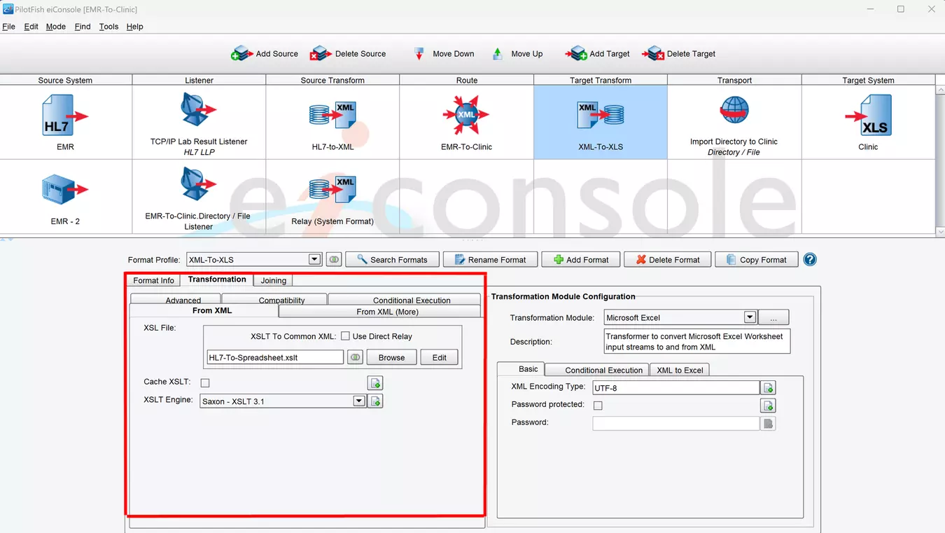
Step 7 – Select Transformer for the Target System
Once the data is on the Target side of the PilotFish workflow, it’s time to transform it so it’s ready to be received by the Target System. This is done the same way as the transformation on the Source side; only the order of operations is reversed. First, a logical mapping is done using XSLT in the PilotFish Data Mapper. This process is identical to the mapping on the Source side, with the only difference being the formats used.
Then, the mapped data is sent to another Transformer. On the Source side, Transformers automate the process of converting non-XML files into XML. These same Transformers do the reverse on the Target side, converting the XML data into a non-XML format.
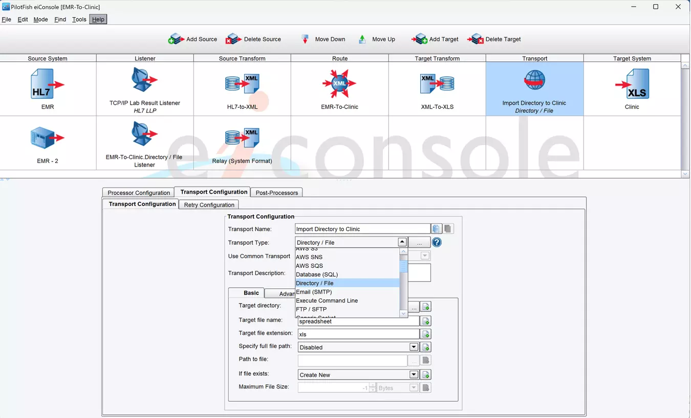
Step 8 – Configure the Transport and Processors
PilotFish Transports communicate with the Target systems and deliver the data to them. As with the Listeners, PilotFish provides a wide range of Transports capable of handling a diverse array of connections to many different systems. Over 30+ Transport Types are included, among them TCP/IP, Command Line, Database Polling SQL Listener, Email (SMTP), FTP(S), Generic Socket Transport, and HTTP(S), etc. Configuring a Transport in the eiConsole is as easy as filling out the configuration panel. Once configured, the Transport will deliver any transactions sent to that Target System.
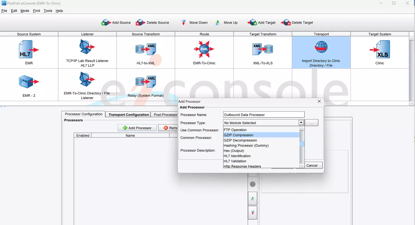
Additional processors can be added before and after the Transport executes if required. These Processors can handle the final small tasks surrounding the delivery of the data to the Target system. The Processors available are the same as those available after the Listener on the Source side.
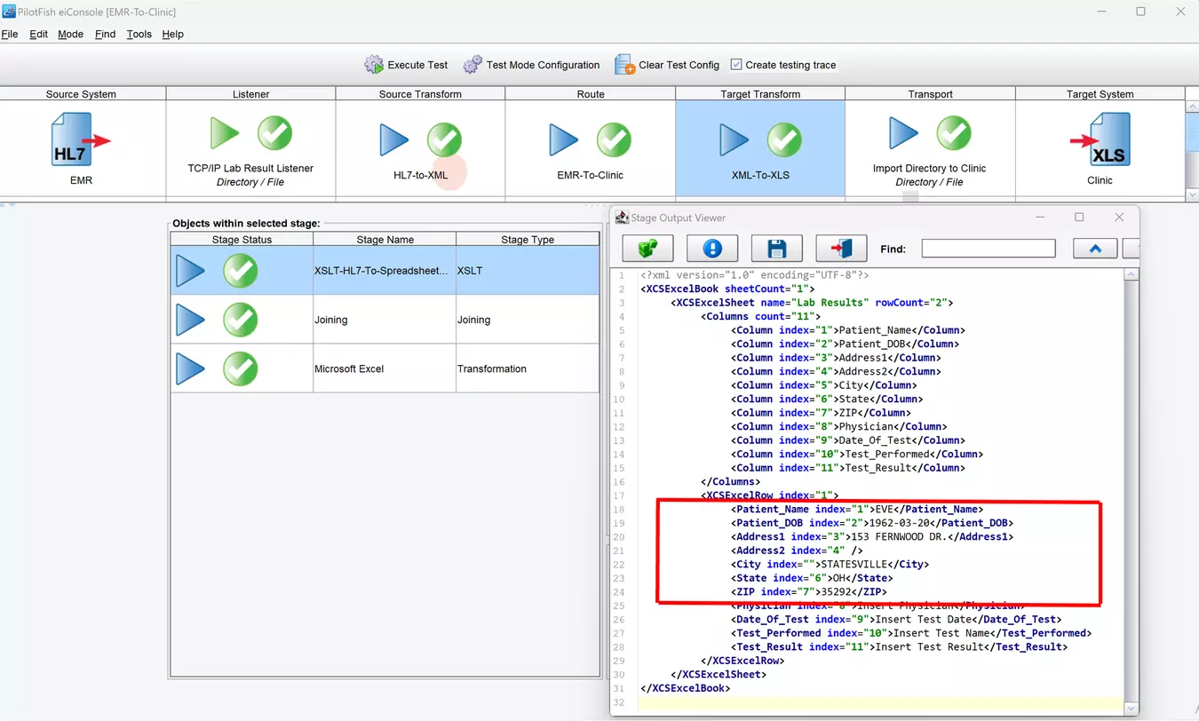
Step 9 – Test the Route
Once the Route has been built, it’s time to test it. The eiConsole comes bundled with a powerful graphical Testing Mode. This mode allows the route to be run from end to end and provides an in-depth look at the processing at each step, making it easier to debug and solve problems. Any Stages that fail provide detailed error messages so that failures can be quickly corrected and retested. You can also start and end the tests at any stage in the Route and manually define the sent data. The Testing mode offers these and other functions to ensure that the Route works just as expected before deployment.
Step 10 – Deploy the Route or Interface
The eiConsole is used to develop the routes and interfaces, but once they are ready, they need to be deployed to the eiPlatform server. In the eiConsole, configurations are simply files on the file system. To deploy, simply navigate to the root directory chosen for these configurations and copy the files over to the other server.
With the eiConsole for Healthcare, your interface can be built and deployed into production 10x to 100x faster! Often, you can leverage an existing interface by cloning and tweaking it, and you’re done.
The eiPlatform is scalable, reliable, manageable and secure. Combined with the eiConsole for Healthcare, it offers a genuine enterprise-class middleware solution for your integration needs.
Simplify Interface Management and Maintenance with the eiConsole
The eiConsole for Healthcare is also designed to simplify the ongoing management and maintenance of interfaces. The Route File Management screen allows you to view all of the entire enterprise’s interfaces on one screen. As the number of interfaces increases, you can filter and sort the interfaces using user-defined fields. Once you have identified a particular interface, it can be “downloaded” from the production eiPlatform, cloned, tweaked, and “uploaded” back to the eiPlatform with just a few mouse clicks.
If you’re curious about the software features, free trial, or even a demo – we’re ready to answer any and all questions. Please call 813 864 8662 or click the button.