Featuring the Graphical Automated Interface Assembly Line – Clone, Tweak, Test and Go!
Meet X12 EDI’s Surging Demand. Configure Interfaces Rapidly. Leverage Reuse.
X12 EDI Interface or Routes Easily Created with PilotFish
According to a recent Healthcare EDI Market report, due to the COVID-19 pandemic and Russia-Ukraine War Influence, the global market for Healthcare EDI estimated at USD 3322.5 million in the year 2022, is projected to reach a revised size of USD 4675.8 million by 2028, growing at a CAGR of 5.9 Percent during the forecast period 2022-2028. This surge in the number of end-users such as payers, providers, pharmaceutical & medical device industries, and others is anticipated to fuel the demand for EDI services or solutions.
In the eiConsole, X12 EDI interfaces can be created and maintained at an unprecedented speed. No coding, no scripting required. X12 EDI interfaces are constructed from a common set of stages via our graphical automated interface assembly line (including Listeners, Processors, Transformations, Routers, and Transports). Drop-down menus, drag & drop data mapping and simple configuration screens make building healthcare interfaces easy.
Interface reuse further slashes implementation timelines. Reuse of interfaces is as simple as Clone, Tweak, Test and Go! Non-developers can do up to 90% of the work too.
Step 1 – Create a New Route or Interface
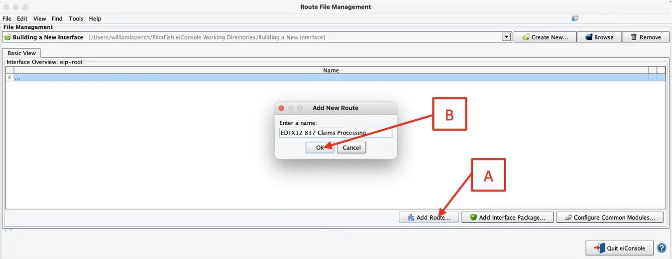
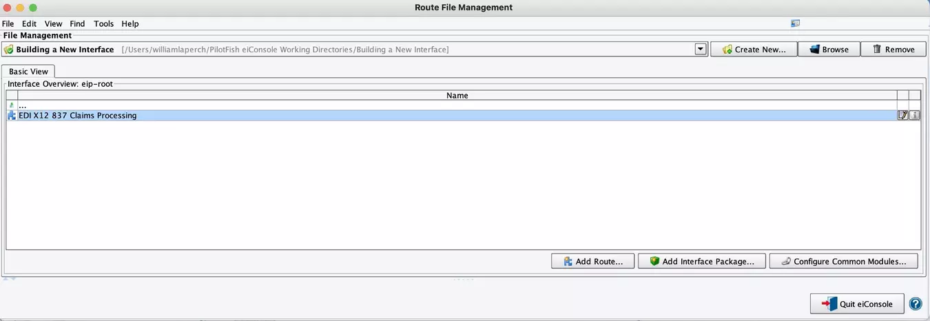
When you open the eiConsole, you will see the Route File Management screen. This is where the interface configuration files are managed. PilotFish configurations are divided into two levels. A single connection between a Source and a Target is a Route and a collection of routes working together is referred to as an Interface. To create a new Route, click Add Route (A), name it (e.g., X12 837 Claims Processing (B) and click OK.
Step 2 – Build the Route
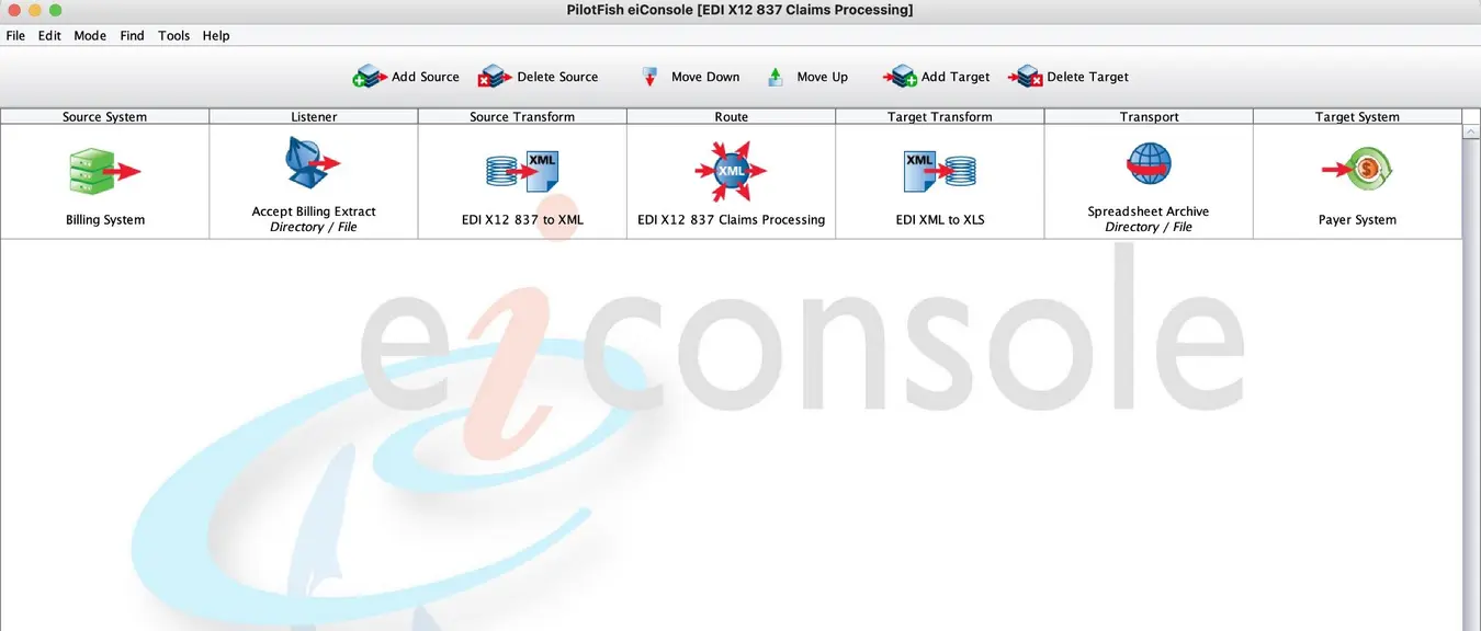
Double-click your Route (C) to open the eiConsole’s main route grid window. PilotFish routes are built in an assembly line fashion. The Graphical Automated Interface Assembly Line (D) consists of 7 stages which are laid out in the grid at the top of the screen. These stages handle processing the flow of data from the source to the target system(s). Regardless of the type of integration, the process is always the same. There is no limit to the number of source and target systems that can be linked in this manner.
Step 3 – Identify Your Source & Target System & Select Representative Icons
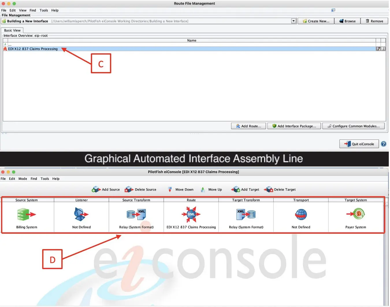
Select the Source System stage to name your source system. For reference, name your Source and Target Systems based on what they are supposed to represent. Next to the System Name field type in “Billing System” (E) then click the Choose Source Icon (F) button.
When the Choose Source Icon pop-up opens, select a representative icon from a library of hundreds of icons. Then click Select (G) to make your choice. Select the Target Stage and follow the same process.
If you would like to add more Source or Target Systems, click the Add Source or Add Target (H) buttons above the grid. Follow the previous steps to name the systems and to select the appropriate icons.
Step 4 – Choose the Listener and any Processors Required
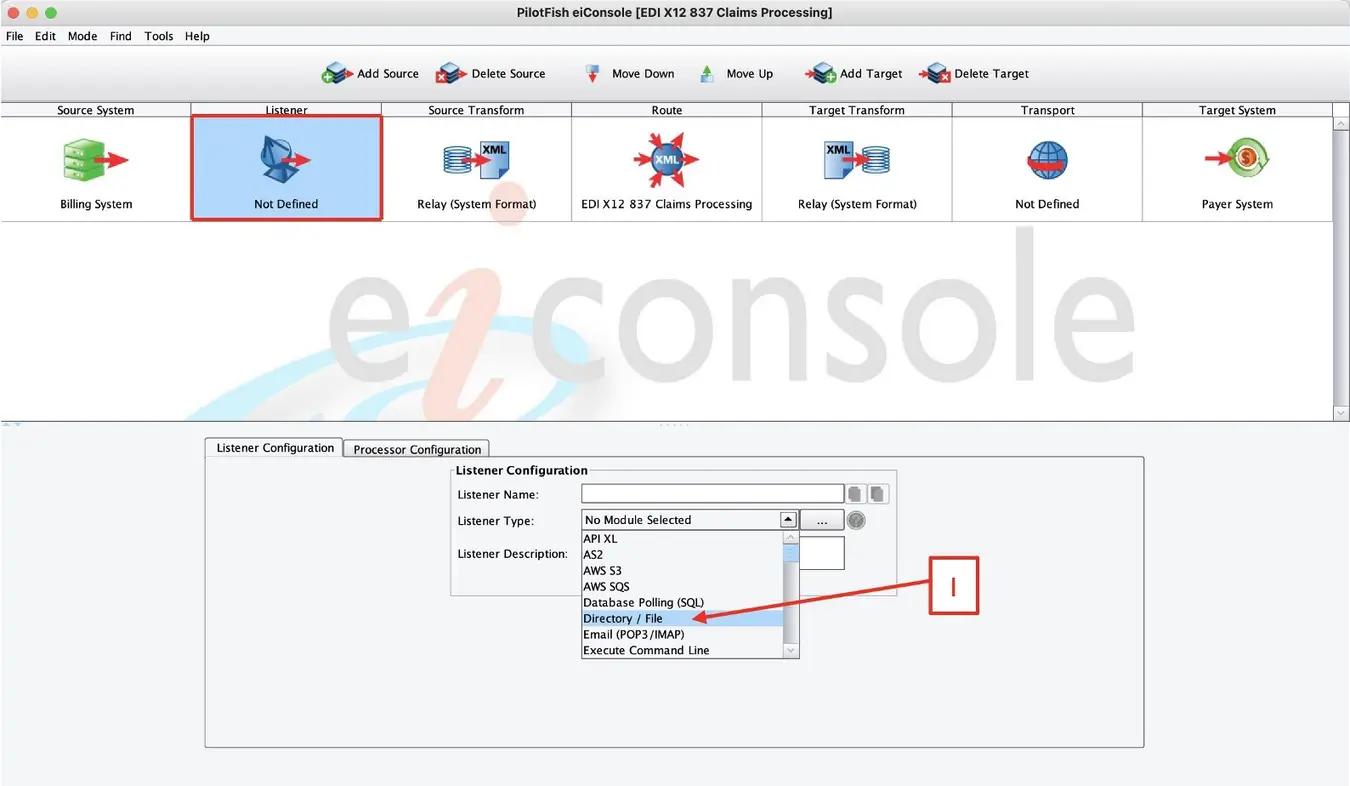
Next, you need to establish connectivity with the Source System. PilotFish retrieves data from the Source System using a component called a Listener. This Listener communicates with the Source System either by polling at scheduled intervals or receiving data in real time. Select the Listener stage to open the Listener configuration panel. PilotFish comes pre-bundled with 40+ Listeners, capable of handling virtually any connectivity option that you might need.
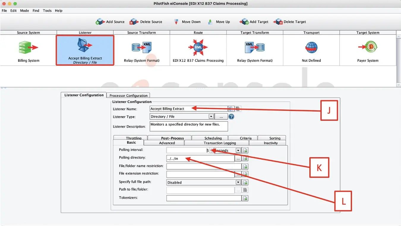
For example, select the Directory/File (I) Listener. After the panel opens, change the default Listener name to “Accept Billing Extract” (J) and set the polling at 10 seconds (K). Next, click the ellipsis (…) button to select the polling directory. You’ll need to paste in the path (L) to where the files you want to read in are located.
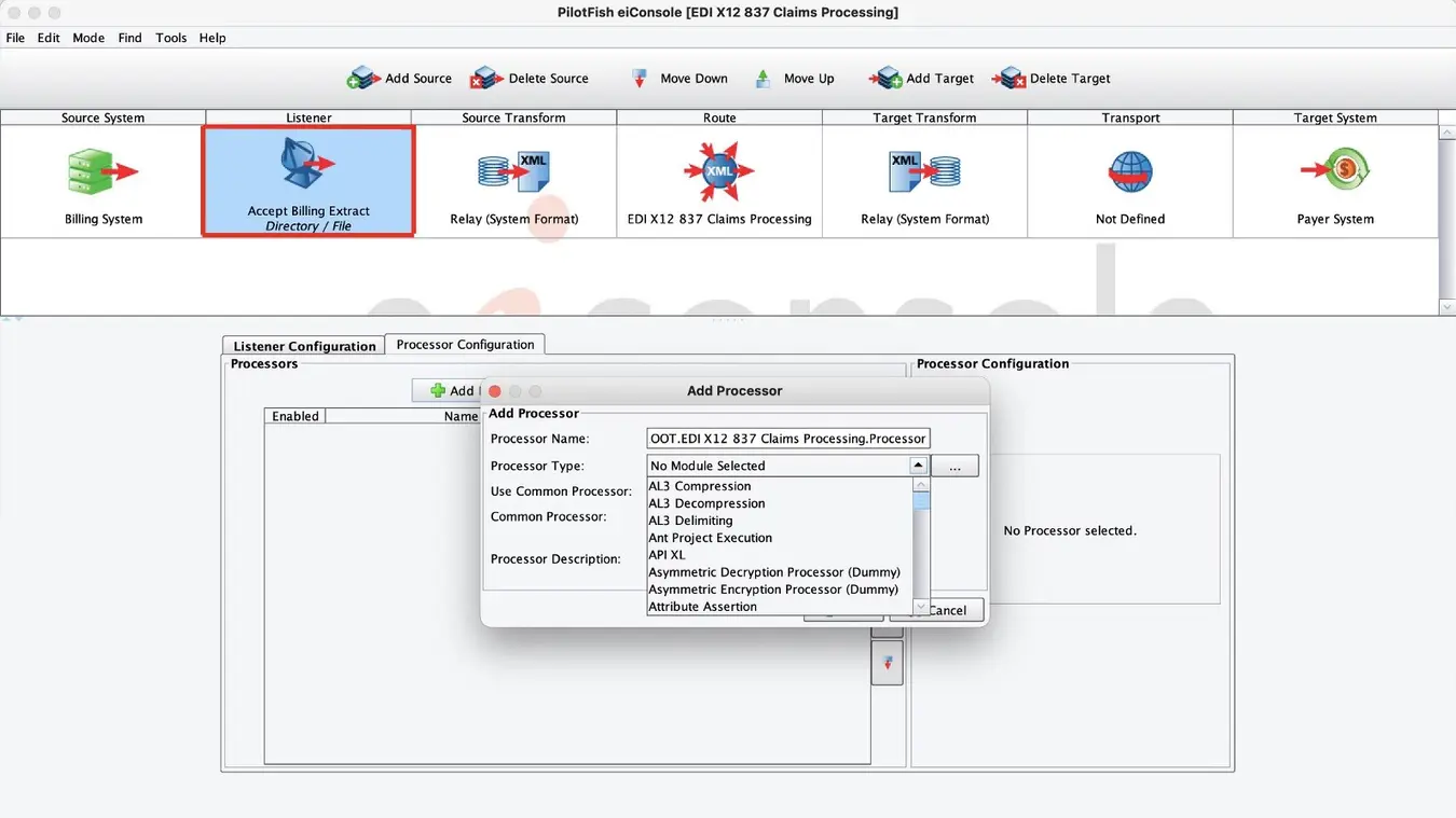
After adding a Listener, Processors can be configured to perform data manipulation on any message/files received. Processors are general-purpose “widgets” that can perform a variety of tasks. You can use a Processor to add decryption, perform authentication or validation. Scroll to choose from 140+ Processors, or add your own using our open API. For this interface, no Processors are needed, so you may move on to the next stage.
Step 5 – Transform the Source Data to a Common Standard
PilotFish data transformation is a two-step process. First, an automated, syntax conversion is performed to translate the inbound data into a parsed, XML representation. The eiConsole includes a number of modules that can be readily configured to handle a wide range of common structured data formats.
Transformation Modules are used to parse data from non-XML formats into an XML representation. Once parsed, the eiConsole’s Data Mapper, which generates XSLT, is used to configure the logical mapping of that format onto another.
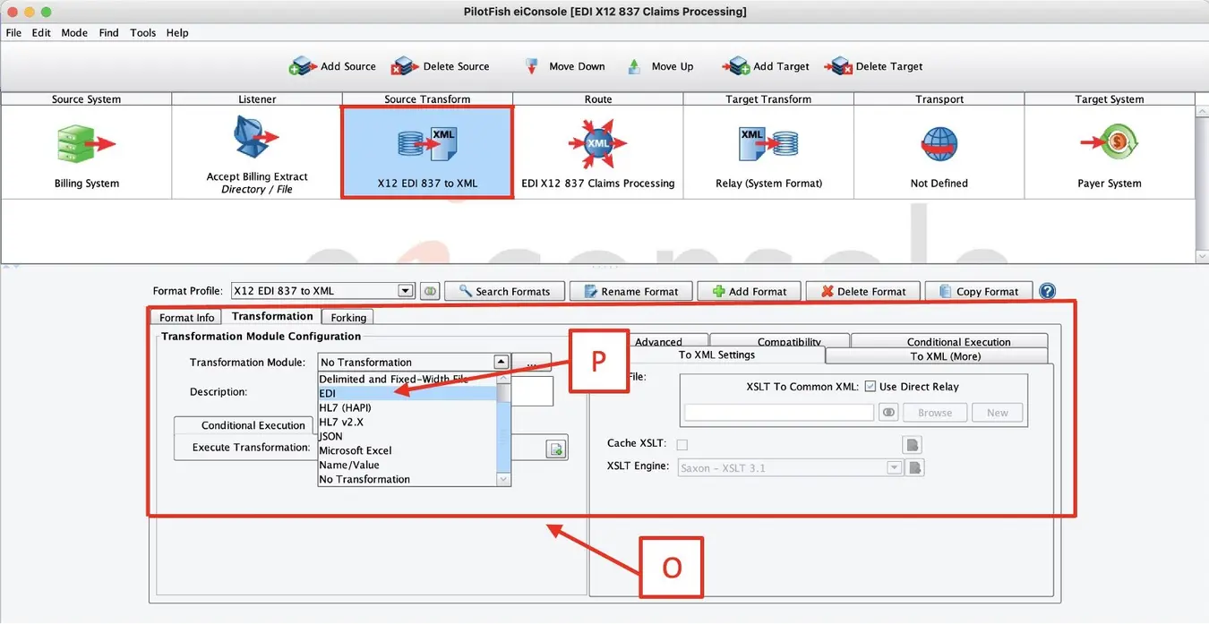
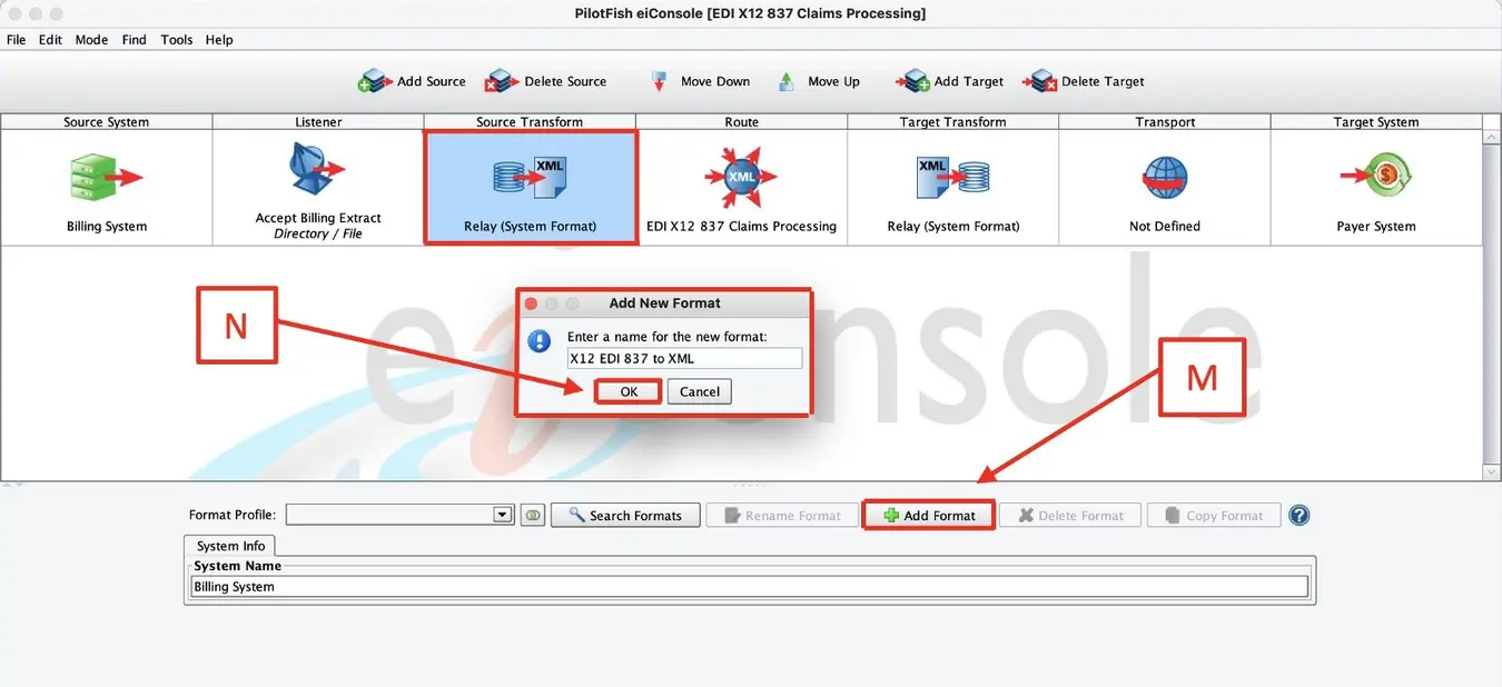
In this example, you’ll need to convert the X12 data to XML. Select the Source Transform stage and click the Add Format (M) button in the bottom panel. In the pop-up panel, name your format X12 EDI 837 to XML (N) and click OK. The Transformation Module and XSLT Configuration panel (O) open. Select PilotFish’s EDI Transformation Module (P), which can consume any ASC X12 EDI transaction based on X12’s published schema and table data. Note that other transformation modules exist to parse a wide variety of formats, including JSON, flat files, and CSVs.
Step 6 – Configure the Routing Module
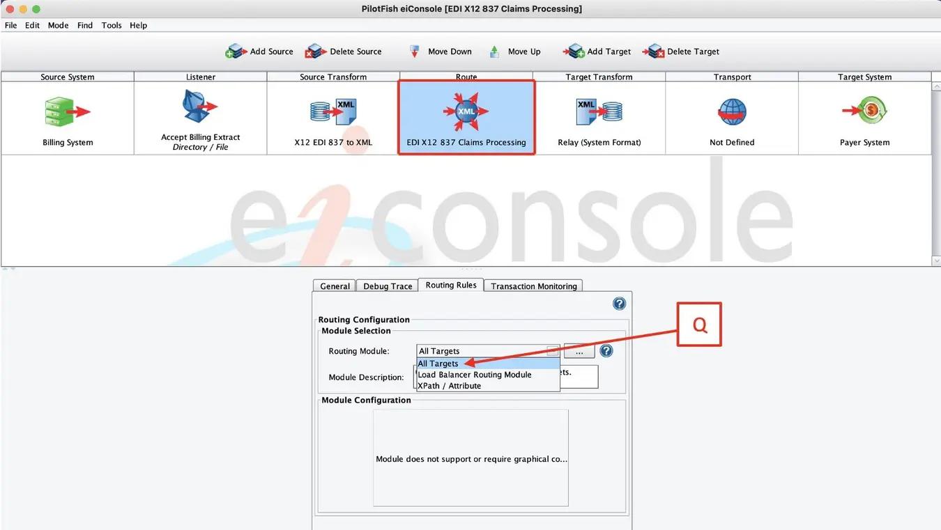
Select the Route stage. This is where you can maintain general metadata describing the Route, specify routing rules and configure Transaction Monitoring. When the panel appears, select the Routing Rules tab. This enables you to route or filter messages to the appropriate target or targets based on the content of the message. From the drop-down, select All Targets (Q).
The Transaction Monitoring tab lets you customize the error notification system used by the interface when in production. This pro-active alerting supplements the traditional, passive logging and audit trail supported and configured in the eiPlatform runtime.
Step 7 – Transform the Data for the Target
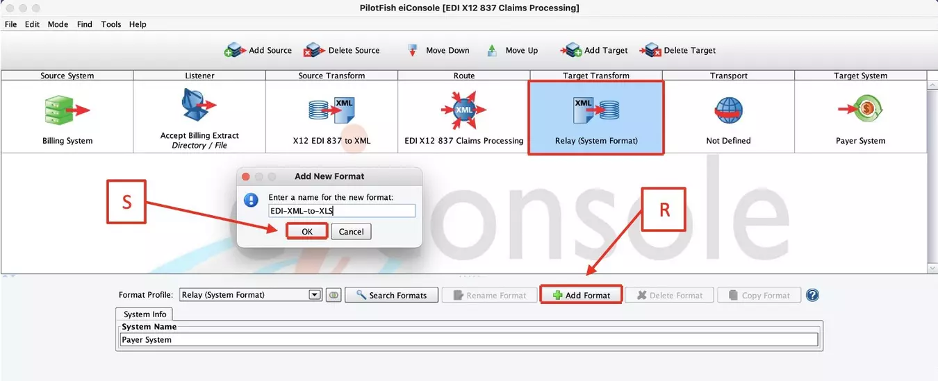
Next, select the Target Transform stage. In this example, this is where you will convert your new XML representation of X12 into an Excel spreadsheet. You’ll use the same two-step process you used for the Source Transform stage, only in reverse. First, click the Add Format (R) button and then enter “EDI-XML-to-XLS”(S) in the dialog and click OK. This opens the transformation panel down below.
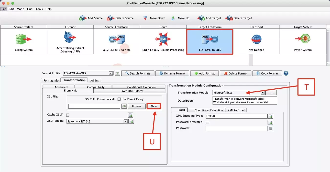
In the Transformation Module Configuration panel, select the Microsoft Excel (T) Transformation Module from the drop-down. This automatically converts an XML representation of Excel into a proper Excel spreadsheet. To create that new XML, go over to the left-hand side, to the XSLT Configuration panel and uncheck the Use Direct Relay checkbox. This will allow you to author a logical mapping, which you can configure by clicking the Edit (U) button to open the Data Mapper.
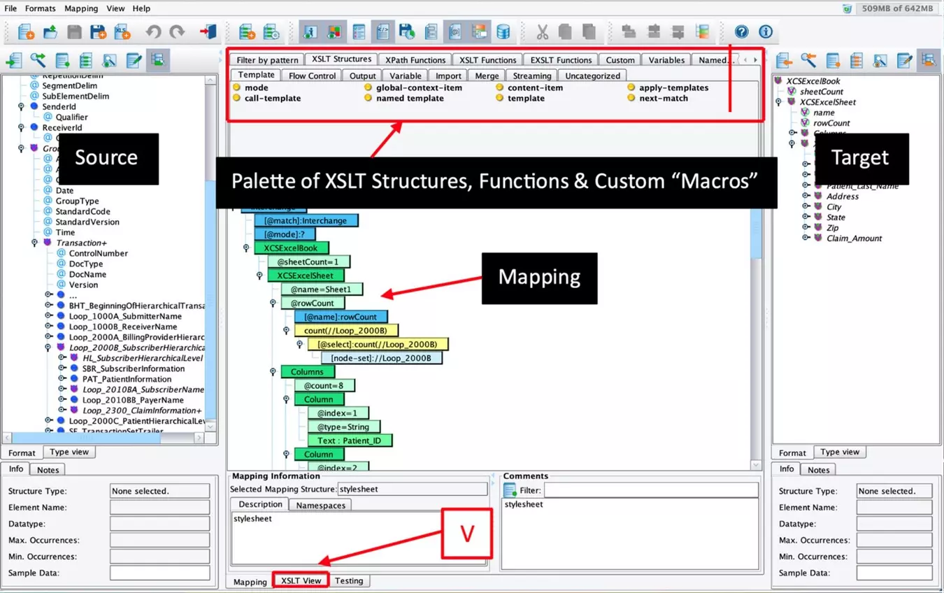
The Data Mapper generates the XSLT that transforms any data format to any other. The tree on the left represents the Source format, and the one on the right the Target format. The panel in between is where we configure the relationship between the two via drag & drop mappings and additional logic. The palette above the center panel includes a library of useful functions for performing additional manipulations, including conditional logic, looping, and table-based lookups. Selecting the XSLT View (V) tab lets users work in XSLT, with changes made immediately available in the graphical view.
While it’s possible to start from scratch, users can also automatically create a baseline for mapping by importing vendor-specific transaction samples, allowing easier data mapping to the specific requirements of the endpoint system.
Step 8 – Configure the Transport
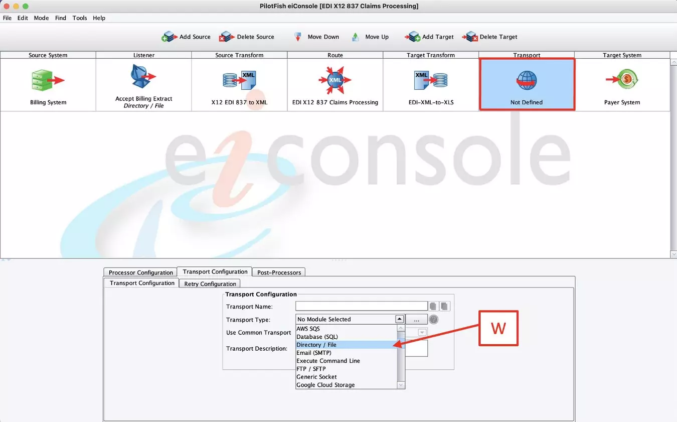
The transport stage is responsible for the transmission of the message or file to its endpoint, or to another route in the interface flow. Like the Listeners, a wide variety of communication protocols, both batch-oriented and real-time are supported with 30+ Transports to choose from. Real-time processes may be synchronous or asynchronous, where real-time responses can be configured to be handled by an associated route.
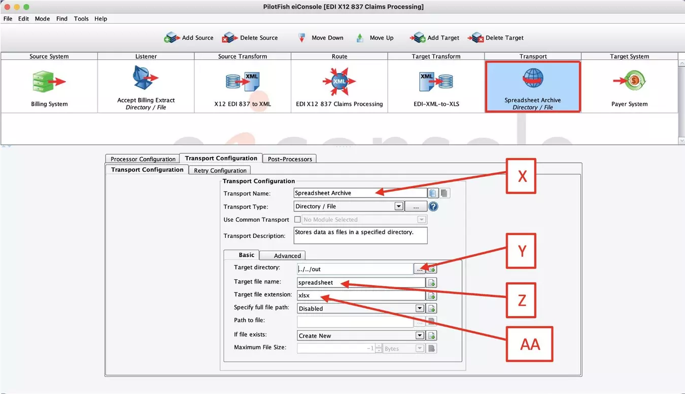
In this example, click the Transport Stage. In the Transport Configuration panel, select the “Directory/File” (W) Transport from the drop-down list. When the configuration panel opens, change the default Transport Name to “Spreadsheet Archive” (X). In the Basic tab, click the ellipsis (Y) button and paste the link to your new “out” folder. Then fill in the Target file name to “Spreadsheet” (Z) and the Target file extension to “xlsx” (aa). As in the Listener stage, processors may be used for preprocessing or cleanup operations.
Step 9 – Test Your Interface End-to-End
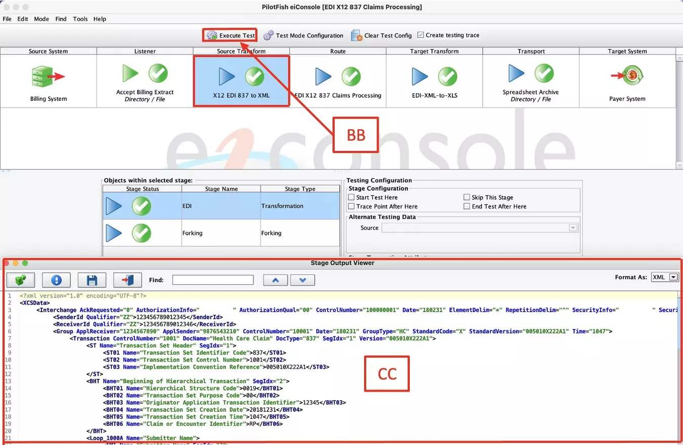
The eiConsole includes a built-in, step-by-step unit testing capability. No compilation or deployment of the interface is required. The testing mode allows the interface developer to test any portion of their configured “assembly line,” inspecting its function, performance, and output.
From the Route menu, select Testing Mode. You can start and stop your test at any stage. Select the Listener stage to begin the testing and provide sample input data. Click the Execute Test (bb) icon, and the blue question marks turn to green checkmarks. If a stage failed, a red X would replace the question mark. You can click any of the stages and in the Stage Output Viewer (cc) view the output of each stage as the data undergoes the transformation and delivery process. Failed stages provide detailed error messages so that these can be quickly corrected and retested.
Step 10 – Deploy Your Interface
Once an interface has been tested from end-to-end, the final step is deployment to an eiPlatform runtime environment. The completed interface is saved as a set of discrete, easily managed configuration files. The promotion of an interface can be managed through your preferred source control system, simple file copy, or a deployment API.
That’s it – X12 EDI interface configuration, testing, and deployment in 10 easy steps. Route your X12 transactions efficiently!
With PilotFish, you can handle virtually any integration requirement, any communication protocol, and any data format with the automated interface assembly line. The PilotFish integration suite solves interoperability challenges without any coding or scripting – and without headaches. PilotFish can make your systems interoperable, now.
If you’re curious about the software features, free trial, or even a demo – we’re ready to answer any and all questions. Please call 813 864 8662 or click the button.
X12, chartered by the American National Standards Institute for more than 35 years, develops and maintains EDI standards and XML schemas.